Explore challenges and solutions in AI chip development
Modeling Large-Core Multimode Fiber-Based Systems in ModeSYS
Large-core multimode fibers are commonly used in automotive and short-distance data transmission links. Depending on the coupling conditions, large cores can support a very large number of fiber modes. Using conventional methods and radial mode solvers to model large-core multimode fibers requires exorbitantly large computational resources.
Without an efficient and accurate method for modeling such systems, successful commercialization of products can become quite challenging. The 2015.06 version of ModeSYS™, a Photonic System Tool, adds a large-core step-index multimode fiber model that allows for the computationally efficient simulation of large-core step-index fibers (with typical core diameters of 200 to 1000 µm) based on the Gloge power-flow approach.
The method is based on models using the Gloge power flow equation, in which the flow of power inside the fiber is modeled as a function of internal angle 1 - 2 :
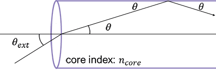
Fiber geometry showing internal propagation angle and external angle, where and is the core index (free-space launch)
The model includes effects such as angle-dependent group velocity accounting for intermodal dispersion, angle-dependent power attenuation accounting for differential mode attenuation (DMA), and power coupling during propagation.
Since ModeSYS models produce optical signals with spatial mode profiles attached, signals at the fiber input are first converted into an equivalent launch intensity as a function of internal angle representation via the use of a far-field transformation. The Gloge power flow equations are solved for each wavelength and each polarization of the optical signal.
As an example, consider a large-core step-index fiber based on model parameters presented in 3 and using a similar set of launch conditions. Ref. 3 provides extracted model parameters for a 1-mm diameter ESKA-PREMIER GH4001 fiber from Mitsubishi, as well as intensity profiles at different fiber lengths for a 645-nm input signal. The following figure depicts the ModeSYS layout:
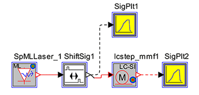
ModeSYS layout for simulating a 1-mm large-core step-index fiber
At the end of simulation, a comparison between the launched and the received signals will show the effects of intermodal dispersion. The figure below shows the peak-normalized input and output pulses, illustrating the expected pulse spreading.
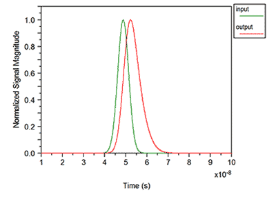
Normalized input and output pulses for 75-m fiber propagation,
showing the effects of intermodal dispersion
You can also see the plots of normalized intensity and encircled angular flux (EAF) as a function of internal and external angle, as shown below.
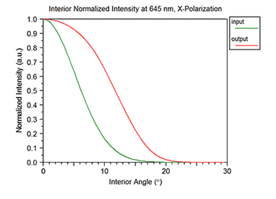
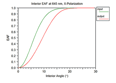
Input and output intensity (top) and EAF versus interior angle (bottom)
for 75-m fiber propagation
As can be seen, propagation down the fiber causes the intensity to evolve towards what will eventually be a steady-state profile.
For more information, please contact photonics_support@synopsys.com.
References
1 D. Gloge, “Optical power flow in multimode fibers,” The Bell System Technical Journal, vol. 51, no. 8, pp. 1767-1783, October 1972.
2 J. Mateo, M. A. Losada, and J. Zubia, “Frequency response in step index plastic optical fibers obtained from the generalized power flow equation,” Optics Express, vol. 17, no. 4, pp. 2850-2860, February 2009.
3 J. Mateo, M. A. Losada, and I. Garcés, “Global characterization of optical power propagation in step-index plastic optical fibers,” Optics Express, vol. 14, no. 20, pp. 9028-9035, October 2006.


